As an open source silicon project, we’re able to make use of best practices from the open source software ecosystem for OpenTitan®. We accept contributions as pull requests which go through code review and continuous integration (CI) testing. The silicon development and testing process brings some unique challenges when compared to a traditional software project.
There are three different ways that we test hardware designs for OpenTitan, each of which gives us a different kind of coverage and also comes with different resource constraints that affect how we run them.
Functional simulation tests
We have a suite of tests which run functional simulations of our hardware designs in software to check how they behave. Simulations are good for deep test coverage because the test bench can inject and inspect arbitrary signals across the design under test. Simulating a design the size of OpenTitan can take a very long time but we do have the flexibility to simulate smaller modules, for example just the AES block. It’s important that we don’t reduce the utility of these tests by reducing the similarity between the simulation and the real silicon that will eventually be produced.
FPGA tests
An FPGA (field programmable gate array) is a special chip that can be reconfigured to resemble a custom silicon design. They run much faster than simulation tests and we’re able to instantiate the full design on the FPGA at once, but we get less flexibility than simulation tests and all testing must be done through firmware on the OpenTitan core and interactions with its IO. FPGA boards are expensive and for OpenTitan we need more than a dozen to keep up with demand and avoid queues.
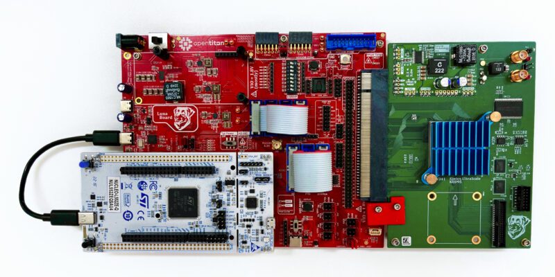
Above is one of the FPGA boards we use: the CW340 from NewAE. As a subsidiary of lowRISC®, we were able to work with NewAE to design this board with OpenTitan in mind. The Xilinx FPGA chip is under the blue heat sink on the green board, while the red board is used for configuration and IO. We communicate with OpenTitan’s IO peripherals using the white STM Nucleo board on the left, which we call HyperDebug.
Silicon validation tests
At the later stages of development for a design,engineering samples of the silicon are used to run the same FPGA test suite to compare results or make up for approximations in the FPGA simulation (for example different clock speeds). Silicon testing serves a specific purpose in being the final truth for whether the chip works as expected. Engineering samples are scheduled for later stages of the development process when the design is mature, so they cannot replace FPGAs in the earlier stages. Production of engineering samples is typically on a fixed schedule so there are a limited number of revisions we can test against.
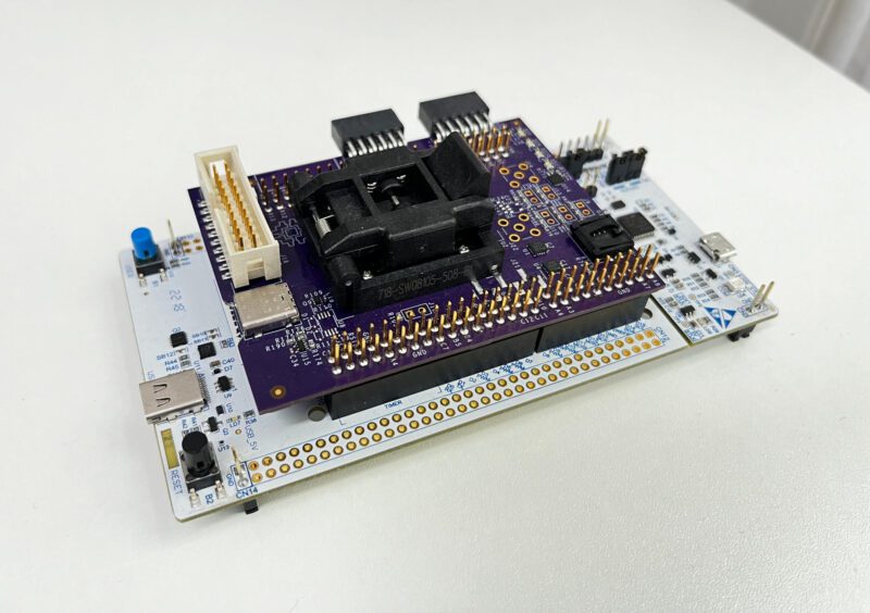
Above is the purple OpenTitan shield board which we use for silicon testing. The engineering sample goes into the black socket on top and the whole thing connects to the same white HyperDebug board as the FPGA testing. This lets us run exactly the same tests on FPGAs and real silicon and compare results.
Assembling the pipelines
We need to balance a few things when putting these tests together into pipelines:
- Speed vs. depth
- Lower resource cost vs. more expensive resource cost
- Public vs. private
We have two CI pipelines: one which runs for every pull request and another which runs nightly against the latest upstream versions of our supported branches. Pull requests are updated very frequently at our current rate of contributions, so we need to ensure that the pull request CI does not consume too many resources and executes quickly in order to ensure a quick feedback loop for contributors. We balance this with ensuring that it provides enough test coverage to keep everything running smoothly without disrupting any other engineers. To cover the gaps, our nightly CI aims for maximum coverage and is able to use more resources and take more time.

Pull request pipeline
The pull request CI pipeline starts with some linting which helps ensure a level of quality for submissions and also saves our reviewers some time. We also run some software unit tests and documentation builds here, as is conventional for an open source project so we don’t need to discuss them further. For hardware testing we run a subset of our simulation and FPGA test suites. For simulations, this means only running some essential “smoke tests” to prevent major regressions in our testing setup. The full FPGA test suite supports running each test in multiple configurations, for example at different lifecycle stages and at different points in the chip’s boot flow. By default, we run each FPGA test in just one of these configurations for the pull request CI.
Nightly pipeline and private testing
The nightly CI pipeline runs our full suite of simulation and FPGA tests, but can also include silicon testing once we receive engineering samples.
Silicon testing raises the problem of public versus private testing: we cannot make the silicon test results publicly visible for commercial certification confidentiality reasons. More often than not the issues we find during silicon testing are problems with our test rigs or assumptions carried over from the FPGAs, so we prefer to do initial testing in private and release the final results later.
We have a similar problem with simulation tests: some of the commercial simulators we use do not allow us to share run logs outside of lowRISC. To make sure they’re providing utility to outside contributors, we generate summaries of the test runs and any errors that occur. These reports are published to our dashboards where the coverage data is publicly visible. The latest dashboards can be found at our Nightly Reports page.
Future
At lowRISC and the OpenTitan Project we are constantly innovating to use the most up to date technology and systems. This is the same for our CI and DV infrastructure. Lately we have been evaluating tools for estimating silicon area of our designs and tracking CDC/RDC timing lints throughout the development process. Watch this space for future information regarding these improvements.